This series of monthly teardowns started as an experiment in early 2018, and since you good people have been reading them, I will continue to make them. But in fact, finding a new and interesting gadget every month can sometimes be a chore. This is why when readers actually send something they wish to take apart, I am always very grateful because it saves me from having to make a decision on my own. Of course, this also means that you can’t blame me if you don’t like me, so keep this in mind.
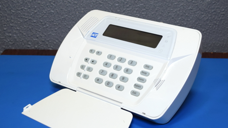
We came here from a tropical paradise in eastern Pennsylvania. The theme of this month is the ADT branded Impassa SCW9057G-433 alarm system. When our kind patron moved, it was obviously pulled down from the wall. As you might have guessed from the model, the device uses 433 MHz to communicate with various sensors and devices throughout the home, and also includes a 3G cellular connection, which can contact alarm monitoring even if the phone line has been cut service.
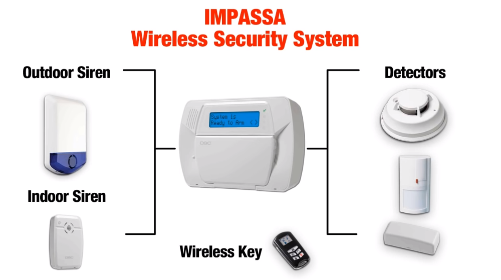
From how many of them are on eBay, and the research I did on some home alarm system forums, it Appear You can actually pick one of them on the second-hand market and spin up your own whole-house alarm system without going through a surveillance company like ADT. Impassa’s extensive documentation covers how to connect and configure the device, as long as the system is not locked when you get it, erasing the configuration and starting from scratch does not seem to be a problem.
If you can combine your own homemade alarm system with one of these units as the core, then the least we can do is take it apart and see what potential modifiable awaits under the shiny plastic casing Good stuff.
Reach out to touch someone
SCW9057G-433 is divided into two parts, with a little mandatory edge, the rear is the battery and 3G2075 “alarm communicator” board, and the front is the main PCB.Or, at least, there is should Become the battery in the rear compartment. Our special sample has been deprived of backup power, so you must use your imagination.
As we can see, the cellular communication board has a SIM slot (no man’s land for one second), an external antenna and a HE863-NAR 3G module, which can provide a considerable 7.2 Mbps through HSPA and has voice and SMS support. I did not expect that there are many other interesting things on the 3G2075, but when you open the RF shield, you will find an unexpectedly large microcontroller.
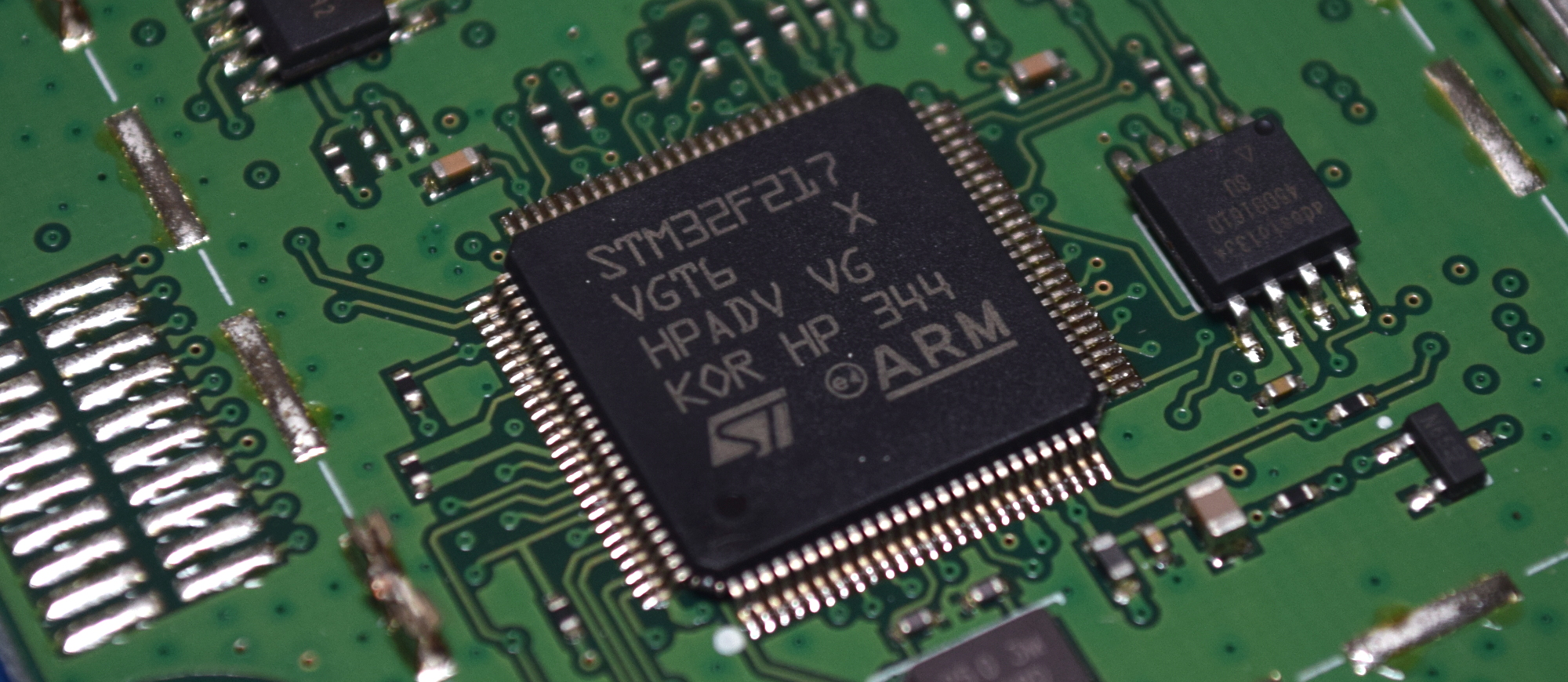
STM32F217VGT6 includes a 120 MHz ARM Cortex-M3 CPU and a series of impressive features, including built-in Ethernet and USB. It is unclear why such a powerful chip is needed to facilitate communication between the main PCB and HE863-NAR, although its hardware accelerated encryption function may be put into use. Next to the MCU is a 16 Mb AT45DB161D serial flash chip. Under normal circumstances, I think it contains the chip’s firmware. But since STM32F217VGT6 already has quite ample on-board flash memory, it seems more likely to be used to save configuration data.
Potato chips hey!
In this series of dismantling, we often face some unfortunate realities, such as epoxy spots and unmarked ICs are now very common and almost become the norm. I usually consider myself lucky if it is possible to identify one or two chips on the board, especially if they are important chips. Fortunately, the motherboard of SCW9057G-433 is full of identifiable ICs.
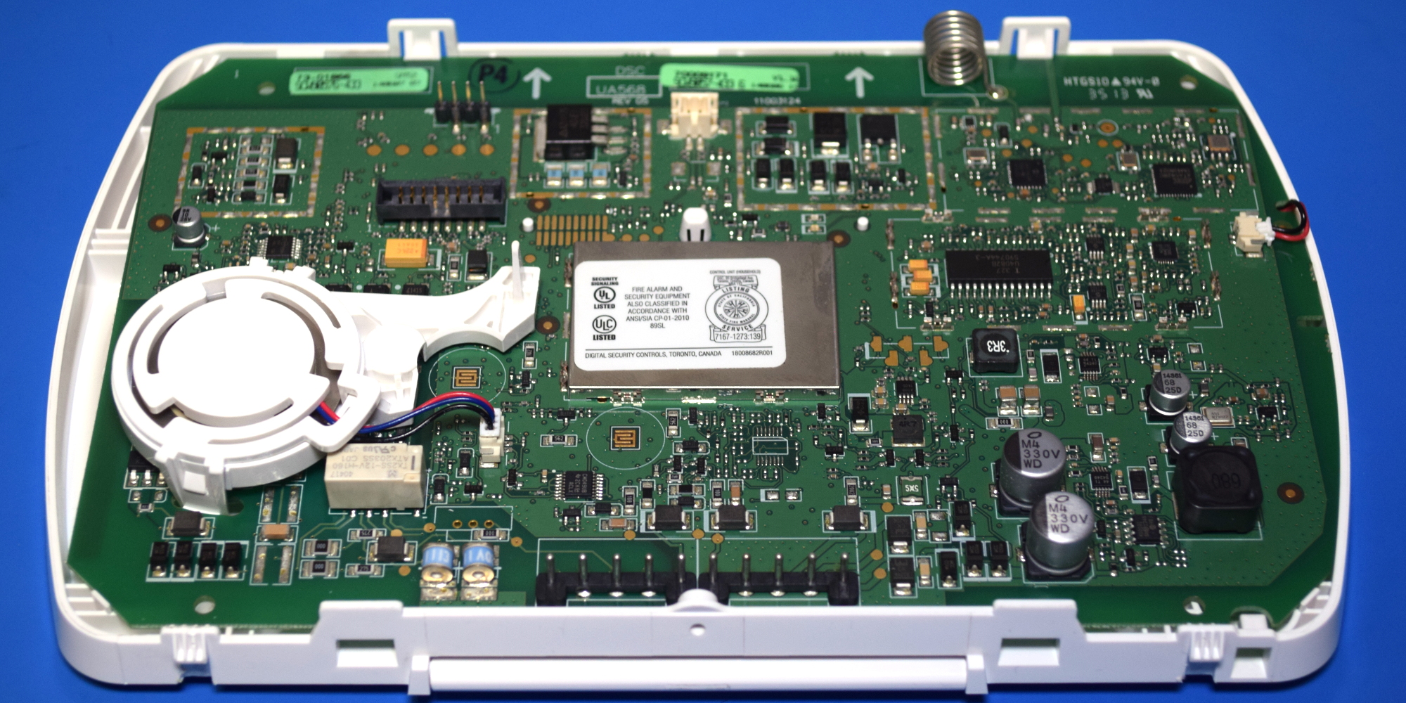
There is a dizzying array of components here, but a closer look we can see that the layout of the board is very logical, making it relatively easy to decompose different functional blocks. Especially because so many components are obviously intended to be isolated from each other with a snap-on RF shield, even though most of the components are not actually installed in the end. For example, by looking at the coil antenna termination position on the top of the circuit board, we can see the hardware responsible for 433 MHz communication.
Half of the equation is the Atmel ATA5428 ASK/FSK transceiver, which has a maximum data rate of 20 Kbit/s and can operate at 433 or 868 MHz. In this case, the radio is paired with a PIC24FJ64GA002 microcontroller in a QFN28 package. Judging from the appearance of the nearby external oscillator, the microcontroller appears to be running at 32 MHz.
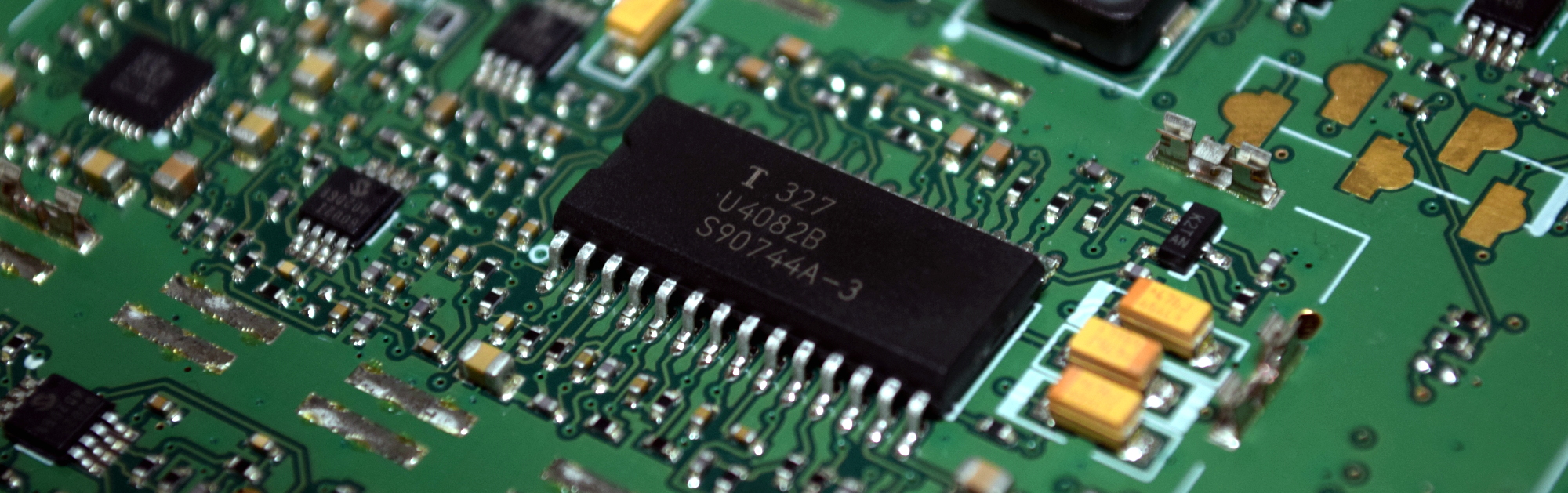
Directly below it, next to the speaker insertion position, we found a slightly uncoordinated SOIC28 chip, labeled U4082B. Located next to the MAX9730E 2.4 watt mono amplifier and a pair of MCP6002 operational amplifiers, at first I thought it might be some kind of audio alarm IC. But in fact it is a speaker chip, and among other things, it is responsible for detecting when the user is speaking. Sure enough, the two-way hands-free is listed as one of the functions of SCW9057G-433, presumably to allow representatives of the monitoring company to talk to customers directly through the alarm panel.
Old and reliable
You can’t seem to walk more than a few millimeters on the board until you encounter another IC to look it up, but of course, you can only read so many regulator specification sheets in a day. So let’s uncover the RF shield and see the real stars in the show.
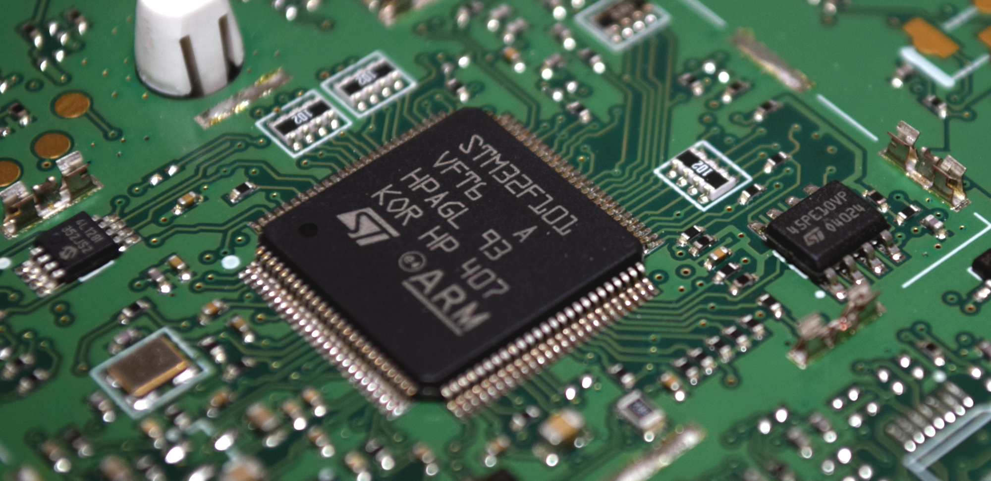
Here, we can see three French fries in their natural habitat. In the center, we have STM32F101VF, which has much lower capabilities compared to the STM32F217 used in the communication board. The 36 MHz ARM Cortex-M3 chip has almost no bells and whistles of the newer F2 series, but it is a reliable workhorse, and Impassa may have gained experience from previous products. On the right side of it, we see an ST brand 45PE10VP 1 Mb serial flash memory chip, and on the left side, a Microchip 24LC128 128 K I2C EEPROM. Between the two external chips and the 768 Kb onboard STM32F101VF, the system seems to have a lot of room for development.
By the way, as early as 2018, Aaron Christophel opened a robot vacuum cleaner and found a very similar MCU. As we expected from this prolific hacker, he started to develop his own firmware for the cleaning robot, part of which involved getting the chip to work in the Arduino environment. It is not clear to what extent he adopted this concept, but if anyone wants to accept the challenge of creating a custom firmware for the device, it at least sets a precedent.
Tamper-proof packaging
Particularly keen readers may have noticed, but before ending this disassembly, I want to point out an interesting little feature of SCW9057G-433: tampering detector. This feature is actually referenced in section 3.5 of the manual and is described as a way for the unit to determine if someone is trying to remove it from the wall.
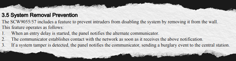
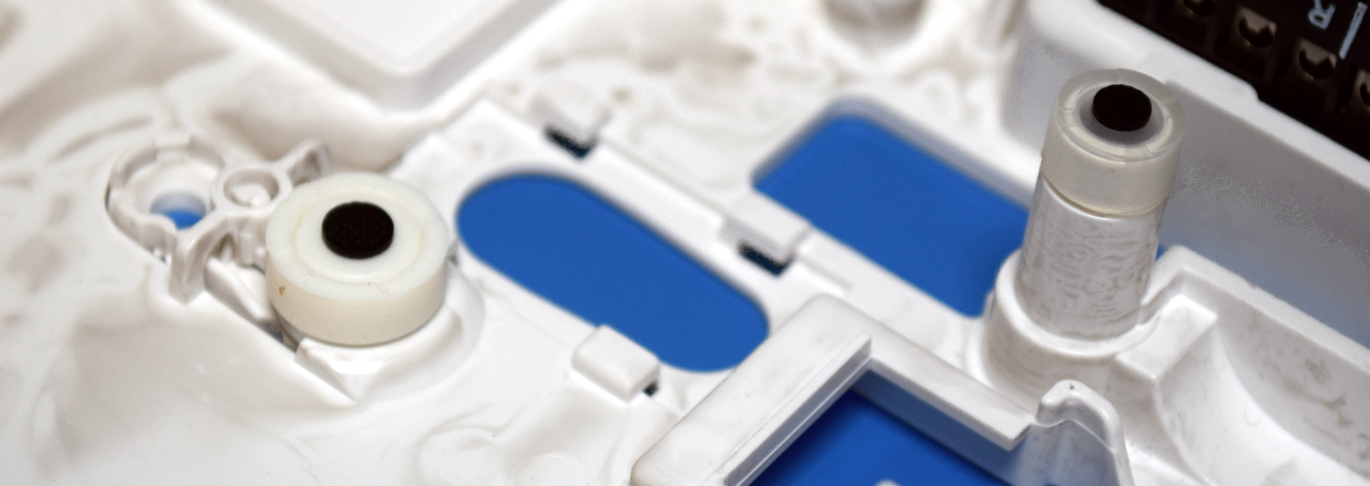
Just like the VeriFone MX 925CTLS that I liberated from the discontinued toy R Us in 2018, this is achieved using a series of strategically placed plungers that push the traces on the PCB. Essentially, it is an open-air momentary button that will remain closed as long as the casing of the device is not opened. There is a pad on the back of the communication board, and there are two pads on the main PCB.
Shell tamper pad
Rear tamper pad
The first one is connected to a small lever. When SCW9057G-433 is screwed to the wall, this lever will be pushed so that if someone takes it off, the alarm will sound. The central pad on the front PCB corresponds to a rod connected to the back panel of the chassis, which is obviously to alert the system when the panel is opened. The third pad does not have any obvious matching, so I can only assume that its counterpart will be mounted on the battery, or maybe some chassis component that holds it. This will allow the system to detect if someone is smart enough to try to cut the battery out of the side of the panel while it is still on the wall.
Second life, or is it good enough?
We have a bunch of recognizable chips, a microcontroller that we have seen programming through the Arduino IDE, and some very obvious programming header files. So what hinders the open source alternative firmware of SCW9057G-433?
Well, on the one hand, you still need to do a lot of reverse engineering before making a real practical firmware. It may not be a problem to have the MCU talk to the LCD and keyboard, but it just scratches the surface. If you want to give it a try, we have introduced some STM32 reverse engineering, they should get you in the right direction.
In other words, the bigger problem may just be that the custom firmware is not real need For this device. The documentation for Impassa seems very special, unless you unfortunately get one of these units locked by the previous user or installer, you should be free to pair it with your device and configure it as you see fit .
Although we like to see proprietary code obscured by the brilliance of open source software on Hackaday, I admit that occasionally you have to choose to fight. Although to be safe, I might ask Aaron Christophel if he wants a new toy to play with.
The equipment you see here was generously provided to us by one of our outstanding readers. If you have an interesting piece of hardware that just occupies the space around the store and want to donate it to our ongoing series of dismantling activities anonymously or in other ways, please feel free to leave us a message.