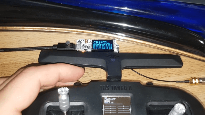
For those who build their own remote control equipment (such as RC ship and four rotor UAV), having good transceiver settings is an important factor in the final availability of their construction. Many transmitters are available in the 2.4 GHz band, but some transmitters operate at different frequencies, such as the 868 / 915 MHz band. TBS crossfire is such a transmitter. Due to its remote performance, it has become a popular model.
When [g3gg0] purchased the crossfire device for his UAV, he found that the receiver module only included a PIC32 microcontroller and an sx1272 Lora modem. This made him think about whether the RF protocol was easy to decode. Facts have proved that this is not trivial, but it is not impossible. First, he built his own SPI sniffer using the cyc1000 FPGA board to display the exact register settings sent by PIC32 to sx1272. Crossfire uses channel frequency hopping. You can easily find the frequency hopping sequence by looking at the register settings.
Once this problem is solved, the next step is to find out what data is passing through these channels. Packets seem to be built in a simple way, but they contain an unknown CRC checksum. Fortunately, brutal coercion is not difficult; Checksums are most likely used to prevent the receiver from receiving signals from different transmitters.
[g3gg0] blog post details crossfire’s protocol and the reverse engineering process required to obtain this information. The final conclusion is that although the protocol is efficient and robust, it does not provide security against eavesdropping or intentional interference. Of course, this is very good for most RC applications, as long as users know this fact.
If you like decoding RF protocols, you may also want to try using a logic analyzer. However, if you just want to copy the signal of an existing transmitter, it may be easier to press a few buttons.
