[Petteri Aimonen] Present to us Modular differential probe, As his chance to enter the 2021 Hackaday Awards.
This project demonstrates a simple and complete implementation of a differential-to-single-ended preamplifier, which allows detecting differential signals and feeding them to an oscilloscope via a BNC cable.

It implements a classic instrumentation amplifier, in which we have two amplifier stages. If necessary, the first stage provides us with a gain of 1 or 10, and the second stage has a gain of 2.
The remaining circuit is a power supply, used to generate the necessary dual-rail power supply to power the operational amplifier. There are many filters on these output rails and the USB power input to try to exclude all switch-mode power supply noise from the signal path.
There are several interesting design options, including the use of PCB material for long detachable probe arms that integrate PCB spark gaps to provide the first line of defense and prevent ESD from reaching the more precise parts of the system.
Why this is useful
There are two main types of signals that our electronic engineers care about: single-ended and differential mode.
For the first type, the signal is transmitted through a single wire, which is defined as taking the public system ground as a reference. The current flows along the wire and returns to its source along the path of least resistance, at least at low frequencies. At higher frequencies, the path of least inductance is more relevant. As long as you design the PCB correctly, all of this is fine.
Coupling from adjacent wires due to mutual capacitance and inductance, and noise in the reference ground, all of which will destroy the signal we want to pass through the wire.
As the frequency increases, especially when you are dealing with sharp edges, plus all the extra odd harmonic power, things start to get very fast.The way we deal with this problem is to use Differential mode signal. This is some concept of reference grounding, instead of a single wire, we send the signal to a pair of wires, where the voltage the difference A signal is formed between the wires. Any external noise that leaks into the wire pair will (hopefully!) affect the two wires equally, forming what we call a common mode component. When you look at the difference, this common mode noise disappears. (our own [Bil Herd] I talked about this some time ago. )
When probing a circuit, it is worth having the correct type of probe and understanding the effect of the probe on the circuit in operation. If you have a single-ended signal and want to view it on an oscilloscope, you can choose passive or active probes. Usually the most commonly used is some kind of passive probe. These are usually available in 50 Ω and 1 MΩ versions, and you need to be careful to use the correct probe type for your application.
In order to detect differential signals, you can use a pair of probes, one for each signal line, and then use the mathematical differential function of the oscilloscope to display the signal. This is usually a desperate measure, and what you really want is a differential front end in hardware. You need a differential active probe.
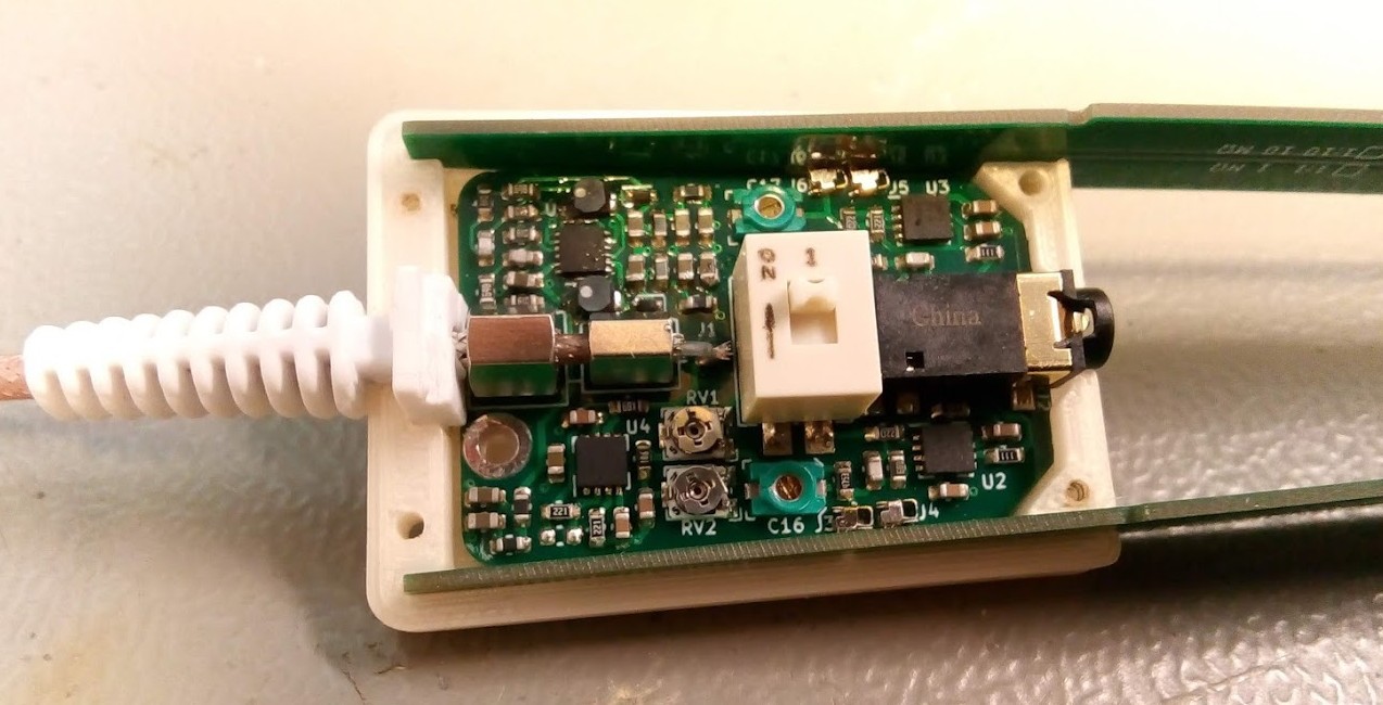
The circuit may be simple, but don’t underestimate how much adjustment it needs to get good performance-as the author describes, a little slippage in the PCB layout can cause some annoying resonances that are difficult to track.
The project is still under active development. The author showed the progress of the project, but if you ask us, it looks pretty good.
Source can Found on his GitHib, It uses all open source tools, so it is also easy to access.