ThunderScope, 2021 Hackaday Award Finalist This is exactly what it does. [Aleska] A modular open source PC-connected oscilloscope is being built, aiming to provide 4 channels and a cool bandwidth of 100 MHz with a lower budget. The detailed project log shows how he understands “oscilloscope technology” in real time, which is a fascinating perspective for navigating the ups and downs of engineers in the rather complex construction process.
How we like [Aleska] I realized early on that keeping the project secret and releasing it only when “I’m done” actually hinders progress, because you can open source from the beginning, record the progress, and get great feedback from the beginning. All of these obvious errors and poor design choices will be discovered and fixed before the hardware is invested. Think about all the time saved. Now this is an attitude of cultivation!
Modular design
A modular approach to reduce the risk of hardware design is a good choice, allowing upgrades or replacement of functional modules to be added when needed. Do I need to replace a single-ended front end with a differential front end, or a front end with other special features? Of course, just pop it out and put it in the replacement part and continue to crack it.
A neat USB 3.0 trick

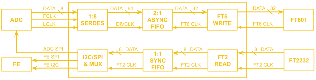
Data path from HMCAD1511 Eight ADCs on 1-GBit/s LVDS channels feed them to the SERDES module on the Spartan 6 FPGA. Among them, FIFO obtains deserialized (parallel) data and synchronizes it to the clock domain of the USB interface, and buffers it during USB busy periods.This allows the use of Ready-made USB 3.0 FIFO interface chip Deal with all those messy interfaces from our good friends at FTDI.
Next, the ADC itself needs to be configured, and the programmable front end also needs to be configured, not to mention that the FPGA needs to load the bitstream through JTAG during the development process. All these “side channel” things are processed through the USB 2.0 interface chip (also from FTDI).
This A clever trick to plug in a USB 2.0 hub Using the USB 3.0 connector, you can have both a USB 3.0 super-speed port and a high-speed port running in parallel, so you can connect the super-speed port directly to the FT601 interface chip, and insert the hub chip 2.0 path in the USB, and then feed others from the same connector USB 2.0 device. A simple but clever technique that saves costs and reduces complexity!
Sharp-eyed people will notice the lack of some traditional oscilloscope circuit functions, especially hardware triggers. This design relies on the speed of modern PCs so that the oscilloscope application can fully implement this function when all the sample data is input continuously.
We will observe the results with interest.