Long before USB became a flash in the eyes of engineers, powering external devices directly from the PC’s I/O ports was already a thing.Some of us may remember those too common PS/2 The through leads can access the 275 mA current provided through these ports. When USB was first released, it initially provided a maximum current of 500 mA, while USB 3.0 was increased to 900 mA.
For a long time, this kind of power supply was only used to power peripheral devices such as keyboards, mice, and similar small devices, rather than requiring each peripheral device to be equipped with its own power adapter. As the number of gadgets connected to the computer increases, USB will not only become the main way to directly power small devices, but it can also charge battery-powered devices and ultimately provide power more widely.
This brings us to the USB Power Delivery (USB-PD) protocol. Confusingly, USB-PD contains many different standards, from fixed voltage charging to programmable power supply and adjustable voltage power supply. What are the exact differences between these modes and how to use them?
Guide communication
In order to understand how getting power from a USB port works at the hardware level, we will look at a chip that implements USB-PD 3.0 (R3.0) in the following form Microchip UPD350The 3.0 revision of the USB-PD specification supports fixed voltage charging up to 100 W-Standard Power Range (SPR)-with Current R3.1 standard Added support for extended power range (EPR) up to 240 W. This additional power increase is mainly achieved through the use of higher voltages: R3.1 is 48 VDC, and R3.0 is 20 VDC.
Although USB-PD is prominent, it can absorb up to 3.0 A at 5 V without using USB-PD at all. This is also a mode supported by UPD350. This is described in Microchip Application Note 1953 (AN1953) and also:

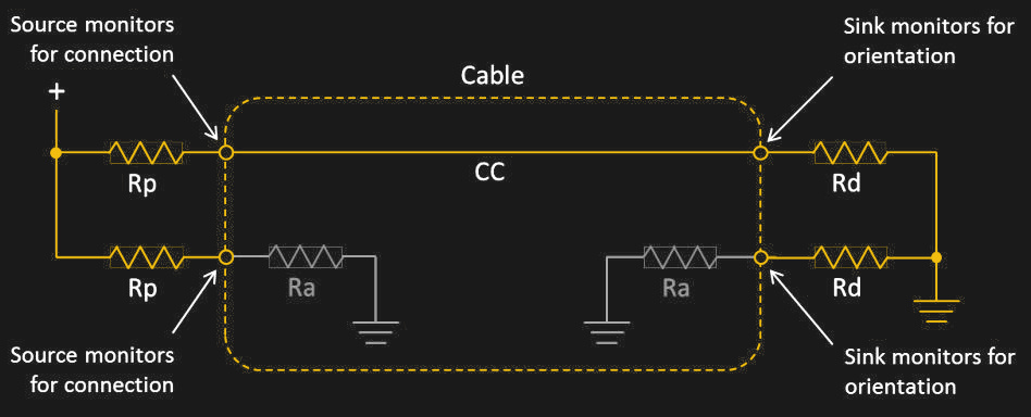
These values are related to the Rp resistance on the side facing the downstream port (DFP), also called the source. By setting this resistance value, the receiver (upstream-facing port, UFP) can determine the maximum current that the source can provide.

In UPD350, the resistance value passes I2When the device is running in DFP mode, C or SPI interface. In UFP mode, the internal CC comparator can detect up to eight different thresholds, which are set by the Rp resistor on the DFP side. One of them is a proprietary option:
• 0.20 volts
• 0.40 volts
• 0.66 volts
• 0.80 volts
• 1.23 volts
• 1.60 volts
• 2.60 volts
• 3.0 V proprietary mode
On the DFP side and vice versa, the receiver resistance on the CC line allows it to know whether it is connected to the UFP. This allows a simple method of transmitting up to 15 watts between the source and sink. In order to obtain more power, it is not so easy to simply increase the current. This is when the fixed voltage mode of USB-PD comes into play.
Universal Ethernet Bus
It may be forgivable to make a comparison between USB-PD and Ethernet. Except for packet-based communication, both use similar MAC and physical interface configurations. When understanding USB-PD, this is actually not a bad model, but USB-PD is its core half-duplex protocol, because it can only communicate using a single CC line.
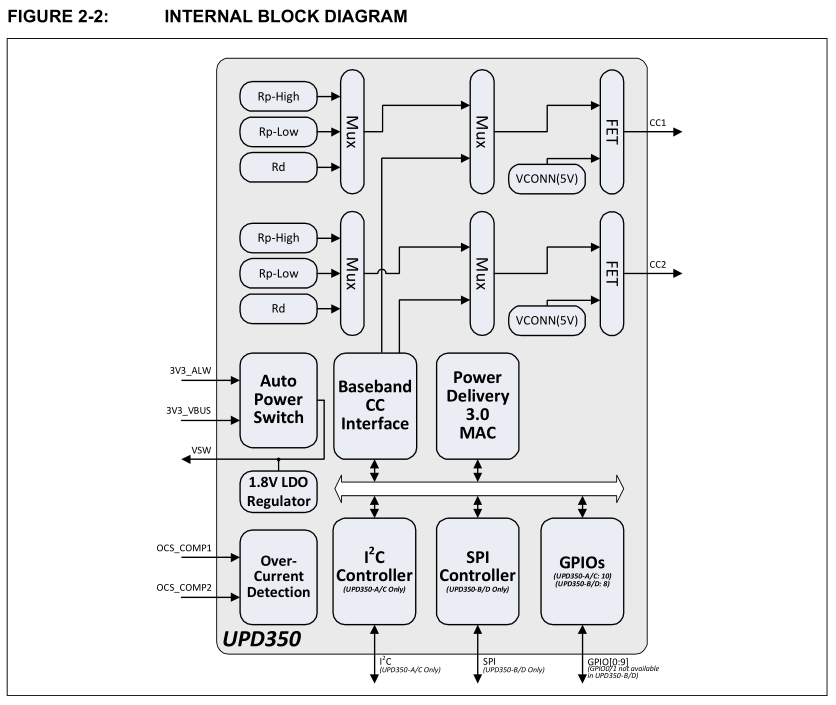
Let us look at the internal block diagram of UPD350 to understand its overall layout:

What is clearly visible in the figure is the Power Delivery 3.0 MAC, which implements the actual USB-PD protocol and also provides a2C or SPI controller.This can be considered equivalent to Mac (Media Access Control) and Ethernet or USB (non-PD) MAC. The baseband CC interface is the physical layer (Physical layer) Convert between MAC and analog front end connected to CC line.
In all communication processes of USB-PD, DFP is the bus master, so all communication is started. As mentioned earlier, USB-PD is half-duplex, using only one CC line for communication, and its baud rate is 300 kbps. CRC32 is used for error detection. All messages use 32-bit 4b/5b encoded bi-phase mark code (BMC), also known as differential Manchester code (DM).
The USB-PD specification details the basic message format of USB-PD, including the payload part:

There are many different data object types:
- BIST Data Objects (BDO)-used for physical layer conformance testing.
- Power Data Object (PDO)-Displays the power capability of the power supply or the power requirements of the receiver.
- Request Data Object (RDO)-Used by the sink to request certain power settings from the source.
- Vendor Defined Data Objects (VDO)-convey vendor-specific information.
- Battery Status Data Object (BSDO)-conveys battery status information.
- Alert Data Objects (ADO)-Indicates events that have occurred on the source or receiver.
Normally, DFP will send its capability list (source capability PDO), and then UDF will use this list to select the appropriate option according to its needs, and send a request for this using RDO data object messages. However, this is not all, because higher voltages and currents are involved, some of which power levels require active “electronically marked” EMCA cables.
With great power
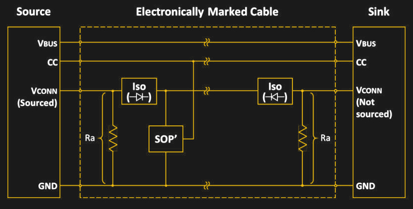
All USB-C cables should support 20 V at 3 A, with a total power of 60 W. In order to be detected by the USB-PD controller as being able to withstand higher voltages and currents, the USB-C cable needs to contain a-called an electronic marking chip, which contains a vendor-defined message (VDM), which contains information about the cable and its functions The details of.
This leads to a slightly more complicated wiring scheme than unmarked cables:

In this case, the same CC signal line is used to query the chip embedded in the connecting cable. If the USB-PD controller is satisfied that the cable meets the required voltage and current settings, it will continue to use power levels beyond the unmarked cable.
This becomes particularly important for the R3.1 USB-PD standard, as part of the fixed voltage EPR mode, the standard increases the voltage to a maximum of 48 V while maintaining the same maximum current of 5 A. Because current is the decisive factor in whether the cable is connected or not, it makes sense when drawing high power levels, but the increased voltage level brings the risk of arcing, especially when the USB-C cable is plugged in or unplugged.
Theoretically, as the higher voltage is firmly locked behind the EMCA cable, the newly designed USB-C connector has extended CC and Vbus pins, which should be able to detect disconnection events with active EPR voltage in time , To quickly reduce the current and prevent hardware damage.
Compare different modes
So far, we have mainly studied the fixed voltage mode of USB-PD. As the name suggests, they support many fixed voltages. For SPR, these voltages are:
All of these can choose 3 A or 5 A current level.
EPR adds the following voltages, all of which are 5 A:
For some purposes, these voltages may not be ideal. In this case, Programmable Power Supply (PPS) or Adjustable Voltage Power Supply (AVS) mode may be more appropriate. PPS mode can be used with SPR, following the latter’s rough voltage level, but allows voltage adjustment in 20 mV steps between 3.3 V and the SPR voltage level plus 1 or 2 V.
The function of the AVS mode is basically the same as that of the PPS, only starting from 15 V as the lowest voltage level and changing to any of the three EPR voltages in steps of 100 mV. Which of these voltages can be used in PPS or AVS mode is the same as regular fixed voltage usage, because the USB-PD controller determines the limit based on the detected hardware.
Universal Power Bus
In hindsight, how computer I/O connectors that were originally designed to transfer data between USB devices eventually evolved into the USB-C and USB-PD specifications that we have today are both logical and perhaps a little absurd. Whether the R3.1 USB-PD specification truly becomes the pinnacle of USB-PD remains to be seen.
Using cables that support USB-C R3.1 EPR can now provide up to 240 W of power, and one might think that this should be enough to charge any laptop now and in the future. At this point, when the USB-C specification sees arcing as a problem, the EPR mode has brought new meaning to the term “hot plug”. This makes the future of USB-PD may bring new improvements to make PPS and AVS modes easier to use, or to add new modes completely to make it easier to set the required voltage and current.
Now, it would be great if you can judge its function by looking at the USB-C port on the device 🙂
